Wi-Fi employee access – Cisco Wireless Controller
In this topic, you will learn how to configure a Cisco Wireless Controller to work together with Portnox™ Cloud and 802.1X RADIUS authentication for Wi-Fi connections.
Cisco Virtual Wireless Controller
This section contains an example configuration for the Cisco Virtual Wireless Controller.
-
In the top menu of the Cisco Wireless Controller web interface, click on the SECURITY
option

-
In the left-hand side menu, select the options.
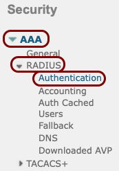
-
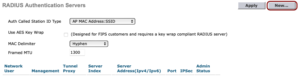
In the RADIUS Authentication Servers pane, click on the New... button
in the top-right corner.
-
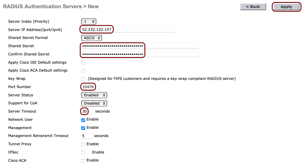
In the RADIUS Authentication Servers > New pane, enter the details of the Portnox Cloud RADIUS server that you created earlier: the Server IP
Address, the authentication Port Number, and the Shared
Secret. Set the timeout to 30 seconds. Then, click on the Apply button in the
top-right corner.
Note:The Support for CoA switch should be set to Enable if you want to use the CoA feature and/or the IPSK feature of Portnox Cloud.
-
If you use two Cloud RADIUS servers in both regions, repeat the above steps for the second RADIUS server.
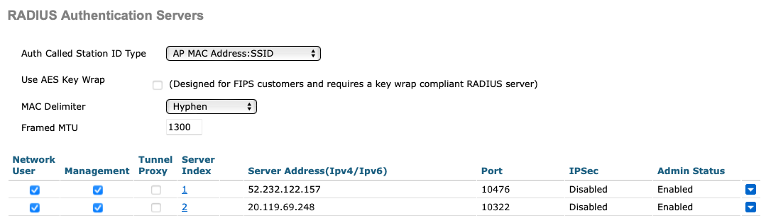
The above screenshot shows an example configuration for two Cloud RADIUS region authentication servers. Adjust the IP addresses and port numbers to your tenant configuration.
-
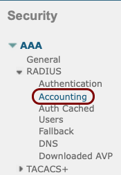
In the left-hand side menu select menu option.
-
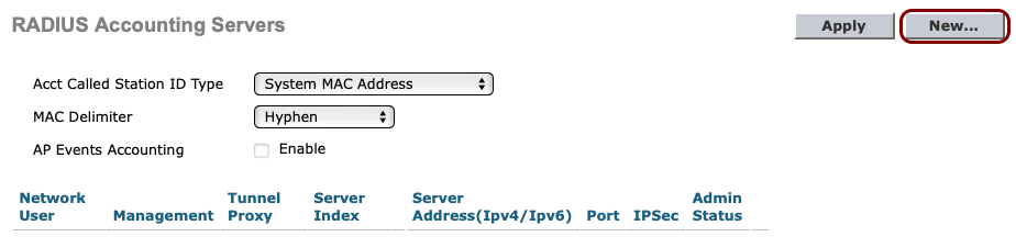
In the RADIUS Accounting Servers pane, click on the New... button in
the top-right corner.
-
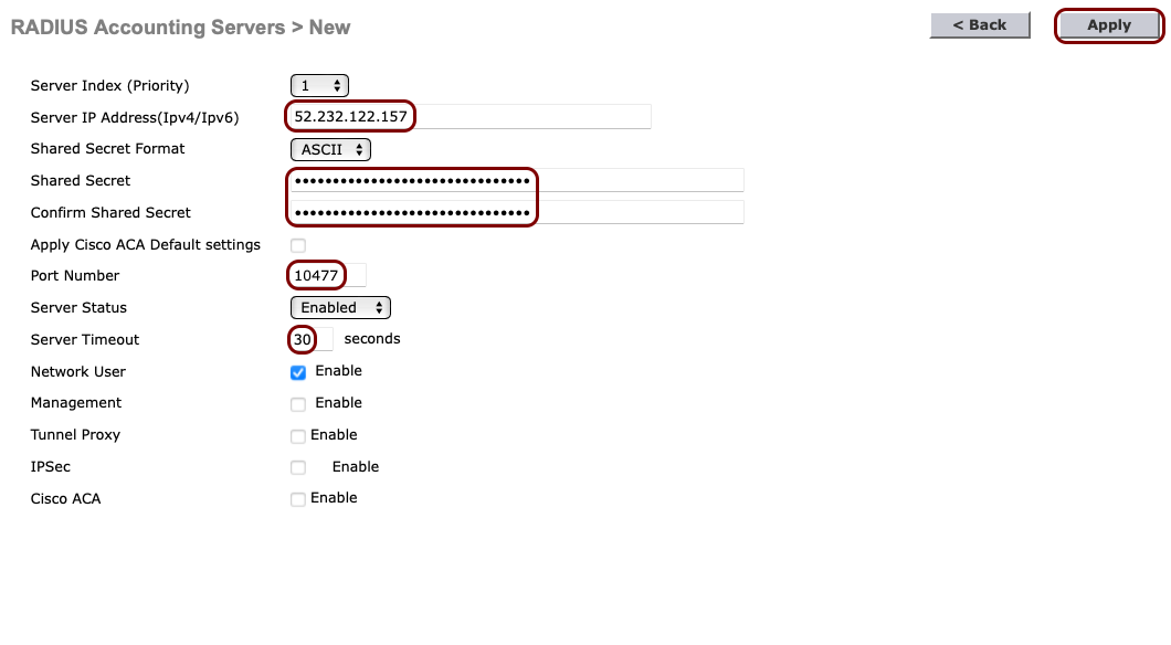
In the RADIUS Accounting Servers > New pane, enter the details of the Portnox Cloud RADIUS server that you created earlier: the Server IP
Address, the accounting Port Number, and the Shared
Secret. Set the timeout to 30 seconds. Then, click on the Apply button in the
top-right corner.
-
If you use two Cloud RADIUS servers in both regions, repeat the above steps for the second RADIUS server.
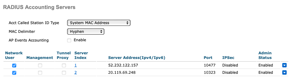
The above screenshot shows an example configuration for two Cloud RADIUS region accounting servers. Adjust the IP addresses and port numbers to your tenant configuration.
-
In the top menu of the Cisco Wireless Controller web interface, click on the WLANs
option

-
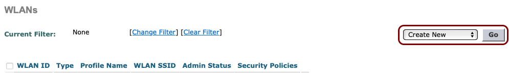
In the WLANs pane, select the Create New option from the drop-down
menu, and then click on the Go button.
 Note:Instead of creating a new WLAN, you can edit an existing WLAN by clicking on the number in the WLAN ID column.
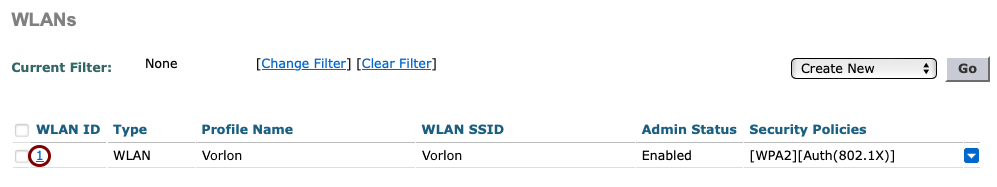
-
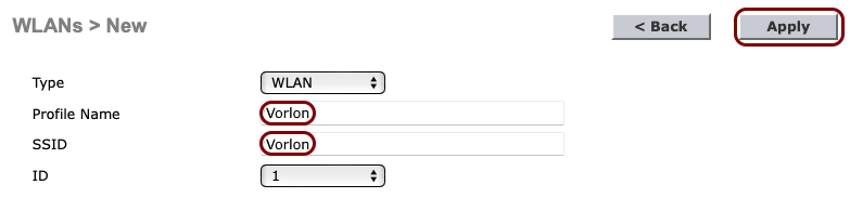
In the WLANs > New pane, enter the Profile Name and the
SSID for the secure SSID that you want to create, and then click on the
Apply button in the top-right corner.
-
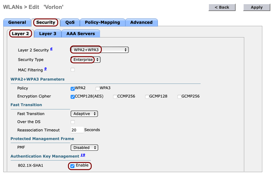
In the WLANs > Edit pane, click on the Security tab and select the
following options in the Layer 2 tab that is opened by default:
-
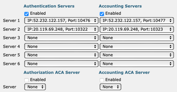
Click on the AAA Servers tab and in the Authentication Servers and
Accounting Servers columns, select the relevant servers that you defined earlier. Then,
click on the Apply button in the top-right corner.
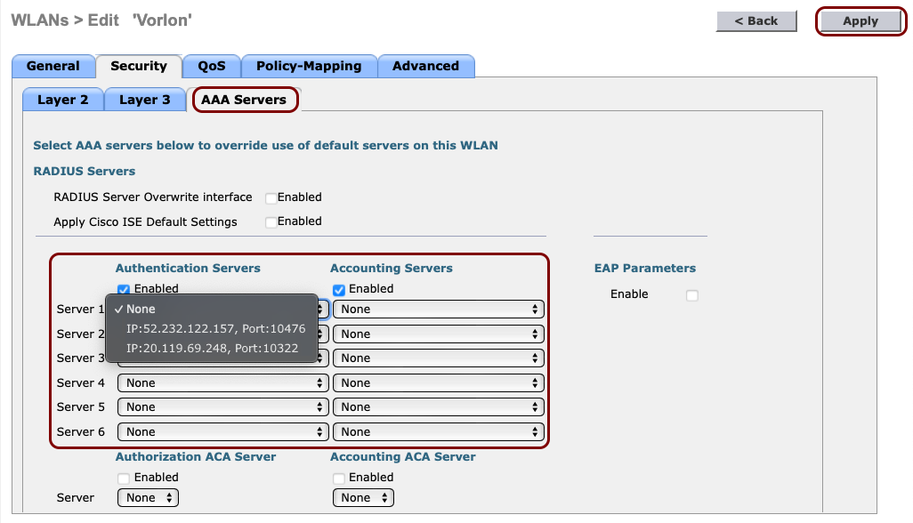 Important:If you want to use the IPSK feature of Portnox Cloud, additionally, activate the RADIUS Server Overwrite Interface checkbox.
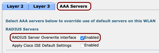
The following screenshot shows an example configuration for two Cloud RADIUS servers. Adjust the IP addresses and port numbers to your tenant configuration.
Result: Your Wi-Fi devices can now access the protected Wi-Fi network, using the Portnox Cloud RADIUS servers for authentication.
Cisco 9800 RadSec
This section contains an example configuration for the Cisco Catalyst 9800 Wireless Controllers and Portnox Cloud RADIUS servers using secure RADIUS (RadSec) connections.
-
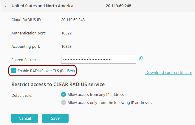
Turn on RadSec connections for your Cloud RADIUS server(s).
-
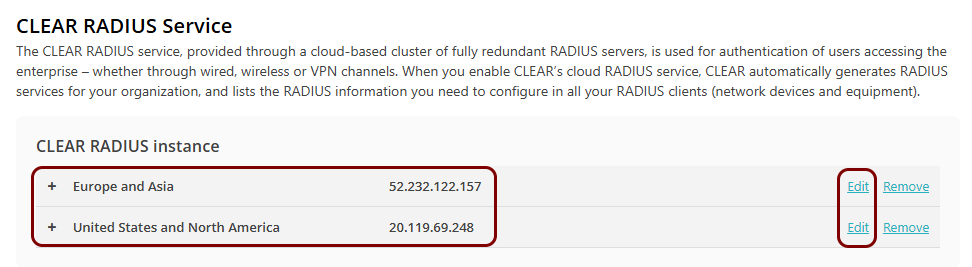
Go to and select the Cloud RADIUS server that you want to connect to using RadSec. Then, click on
the link.
-
Activate the Enable RADIUS over TLS (RadSec) checkbox.
-
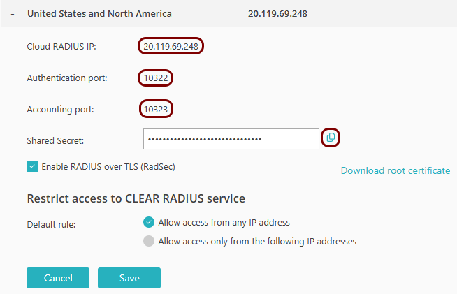
Copy the following information and store it, for example, in a text file. You will need this information
later on in the configuration process:
- Cloud RADIUS IP
- Authentication port
- Accounting port
-
Go to and select the Cloud RADIUS server that you want to connect to using RadSec. Then, click on
the link.