Wi-Fi employee access – Cisco Wireless Controller
In this topic, you will learn how to configure a Cisco Wireless Controller to work together with Portnox™ Cloud and 802.1X RADIUS authentication for Wi-Fi connections.
Cisco Virtual Wireless Controller
This section contains an example configuration for the Cisco Virtual Wireless Controller.
-
In the top menu of the Cisco Wireless Controller web interface, click on the SECURITY
option

-
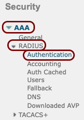
In the left-hand side menu, select the AAA > RADIUS > Authentication options.
-
In the RADIUS Authentication Servers pane, click on the New... button
in the top-right corner.

-
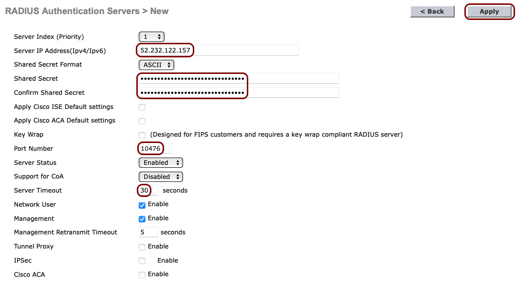
In the RADIUS Authentication Servers > New pane, enter the details of the Portnox Cloud RADIUS server that you created earlier: the Server IP
Address, the authentication Port Number, and the Shared
Secret. Set the timeout to 30 seconds. Then, click on the Apply button in the
top-right corner.
Note:The Support for CoA switch should be set to Enable if you want to use the CoA feature and/or the IPSK feature of Portnox Cloud.
-
If you use two Cloud RADIUS servers in both regions, repeat the above steps for the second RADIUS server.

The above screenshot shows an example configuration for two Cloud RADIUS region authentication servers. Adjust the IP addresses and port numbers to your tenant configuration.
-
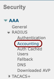
In the left-hand side menu select AAA > RADIUS > Accounting menu option.
-
In the RADIUS Accounting Servers pane, click on the New... button in
the top-right corner.

-
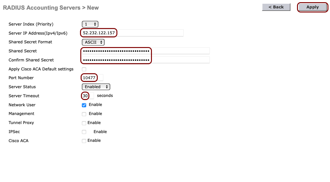
In the RADIUS Accounting Servers > New pane, enter the details of the Portnox Cloud RADIUS server that you created earlier: the Server IP
Address, the accounting Port Number, and the Shared
Secret. Set the timeout to 30 seconds. Then, click on the Apply button in the
top-right corner.
-
If you use two Cloud RADIUS servers in both regions, repeat the above steps for the second RADIUS server.

The above screenshot shows an example configuration for two Cloud RADIUS region accounting servers. Adjust the IP addresses and port numbers to your tenant configuration.
-
In the top menu of the Cisco Wireless Controller web interface, click on the WLANs
option

-
In the WLANs pane, select the Create New option from the drop-down
menu, and then click on the Go button.
 Note:Instead of creating a new WLAN, you can edit an existing WLAN by clicking on the number in the WLAN ID column.
-
In the WLANs > New pane, enter the Profile Name and the
SSID for the secure SSID that you want to create, and then click on the
Apply button in the top-right corner.

-
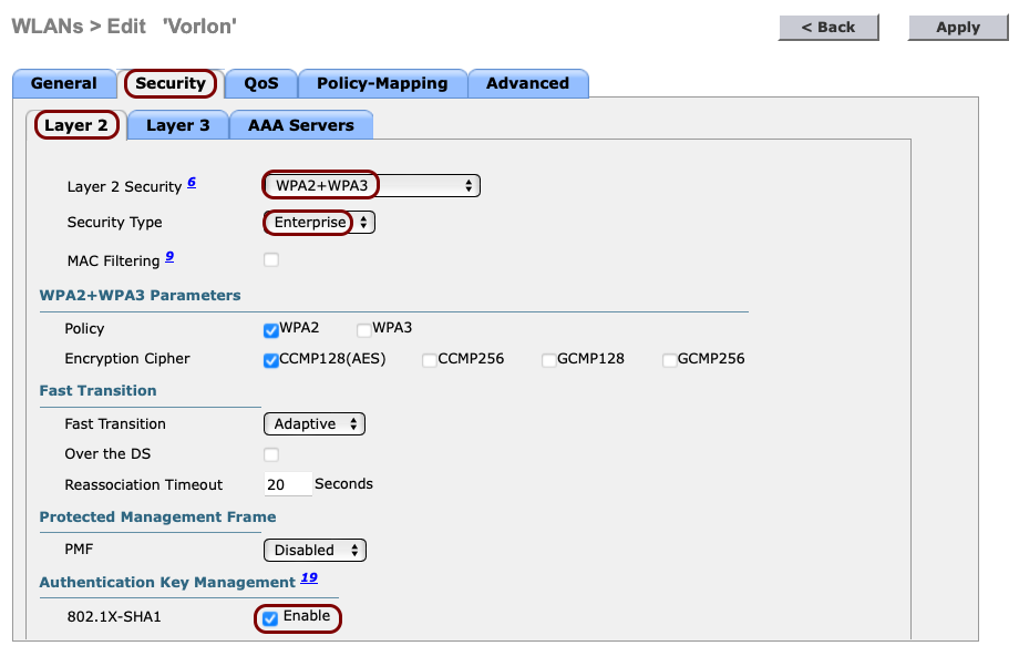
In the WLANs > Edit pane, click on the Security tab and select the
following options in the Layer 2 tab that is opened by default:
-
In the Layer 2 Security field, select the WPA2+WPA3
option.
Note:If you want to use this SSID to connect IoT devices that do not support 802.1x, select the None option and activate the MAC Filtering checkbox instead.
- In the Security Type field, select the Enterprise option.
- In the Authentication Key Management section, activate the Enable checkbox next to the 802.1X-SHA1 option.
-
In the Layer 2 Security field, select the WPA2+WPA3
option.
-
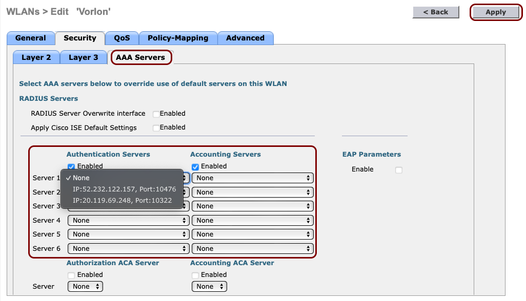
Click on the AAA Servers tab and in the Authentication Servers and
Accounting Servers columns, select the relevant servers that you defined earlier. Then,
click on the Apply button in the top-right corner.
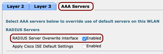
 Important:If you want to use the IPSK feature of Portnox Cloud, additionally, activate the RADIUS Server Overwrite Interface checkbox.
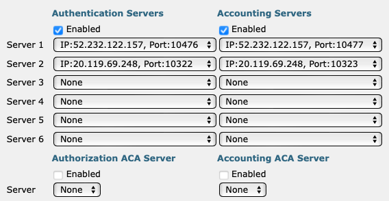
The following screenshot shows an example configuration for two Cloud RADIUS servers. Adjust the IP addresses and port numbers to your tenant configuration.
Result: Your Wi-Fi devices can now access the protected Wi-Fi network, using the Portnox Cloud RADIUS servers for authentication.
Cisco 9800 RadSec
This section contains an example configuration for the Cisco Catalyst 9800 Wireless Controllers and Portnox Cloud RADIUS servers using secure RADIUS (RadSec) connections.
-
Turn on RadSec connections for your Cloud RADIUS server(s).
- Open your Portnox Cloud tenant in a web browser.
-
Go to Settings > Services > CLOUD RADIUS SERVICE > Cloud RADIUS instance and select the Cloud RADIUS server that you want to connect to using RadSec. Then, click on
the ⋮ > Edit link.

-
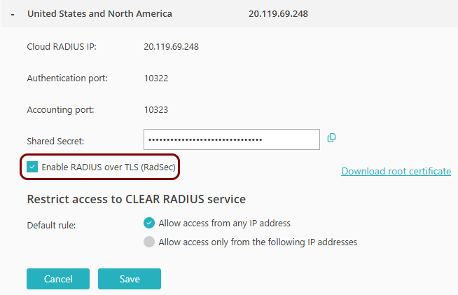
Activate the Enable RADIUS over TLS (RadSec) checkbox.
-
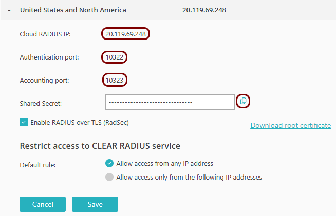
Copy the following information and store it, for example, in a text file. You will need this information
later on in the configuration process:
- Cloud RADIUS IP
- Authentication port
- Accounting port
- Click on the Save button to save your changes.
-
Download the Portnox Cloud RADIUS trust chain certificates from DigiCert.
- Download the DigiCert Trusted Root G4 certificate in PEM format.
- Download the DigiCert Trusted G4 TLS RSA SHA384 2020 CA1 intermediate certificate in PEM format.
-
Merge the certificates into a single PEM file.
The file must have this structure:
-----BEGIN CERTIFICATE----- (DigiCert G4 TLS CA1 Intermediate CA certificate) -----END CERTIFICATE----- -----BEGIN CERTIFICATE----- (DigiCert G4 Root CA certificate) -----END CERTIFICATE----- -
Upload the certificate chain file into the Trustpool.
Navigate to: Configuration > Security > PKI > Trustpoints > Add, then select type as CA Certificate and upload the file.
-
Generate a WLC device certificate.
Follow the official Cisco documentation to generate this certificate on WLC.
Note:The Cisco 9800 WLC requires a device certificate, even if Portnox Cloud is configured for one-way TLS, not mTLS. Cisco’s PKI system enforces this. RadSec will not work unless the WLC has a valid device certificate installed. Portnox Cloud supports optional mTLS and if mTLS is enabled, the WLC sends its device certificate to Cloud. If mTLS is not enabled, Cloud ignores the certificate, but Cisco still requires a valid certificate and a complete certificate chain on the WLC.- Navigate to: Configuration > Security > PKI > Trustpoints.
- Click on Add to create a new Trustpoint for the NAS device certificate.
- Generate a CSR using the WLC interface.
- Submit the CSR to your Certificate Authority.
-
When your CA returns the signed device certificate, merge certificates into a single PEM file.
This file must contain the device certificate (issued from CSR), the intermediate CA certificate (from your CA), and the root CA certificate (from your CA). It must have this structure:
-----BEGIN CERTIFICATE----- (Device certificate) -----END CERTIFICATE----- -----BEGIN CERTIFICATE----- (Intermediate CA certificate) -----END CERTIFICATE----- -----BEGIN CERTIFICATE----- (Root CA certificate) -----END CERTIFICATE----- - Upload this certificate chain file.
-
Configure the RADIUS server on WLC:
- Navigate to Configuration > Security > AAA > RADIUS > Servers and Add a new server, naming it, for example, AAA RADIUS Server.
- In the Server Address field, paste the Cloud RADIUS IP value obtained earlier from Portnox Cloud.
- In the Authentication Port field, paste the Authentication Port value obtained earlier from Portnox Cloud.
- In the Accounting Port field, paste the Accounting Port value obtained earlier from Portnox Cloud.
-
In the Shared Secret field, type: radsec.
Note:Do not paste the Shared Secret from Portnox Cloud.
- Click on the RadSec tab.
- In the RadSec Type field, select the TLS option.
- In the Port field, paste the Authentication Port value obtained earlier from Portnox Cloud.
- In the Trustpoint Client field, select the Trustpoint that you created for WLC.
- In the Trustpoint Server field, select the Trustpoint that you created for Cloud RADIUS.
-
In the Hostname field, enter the hostname of the Portnox Cloud RADIUS server.
To find the FQDN for your Cloud RADIUS IP, see the following topic: What are the fully qualified domain names (FQDNs) of Cloud RADIUS servers.
- Click on the Update & Apply to Device button.
