Guest access – Extreme WiNG
In this topic, you will learn how to configure Extreme WiNG to work together with the Portnox™ Cloud captive portal for guest user authentication.
Before you begin configuring your controller, you must configure the guest network in Portnox Cloud and note down the values of the fields: IP (for walled garden) and Captive Portal URL. You will need these values later. We recommend that you keep your Portnox Cloud configuration open in another browser tab for easy copying and pasting.
-
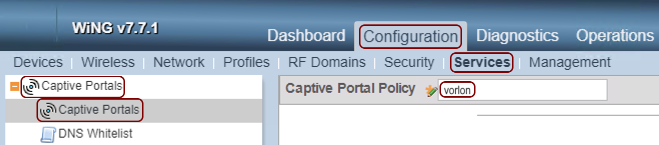
In the WiNG web interface, navigate to: and in the Captive Portal Policy field, enter a new captive portal policy
name.
-
In the Basic Configuration tab:
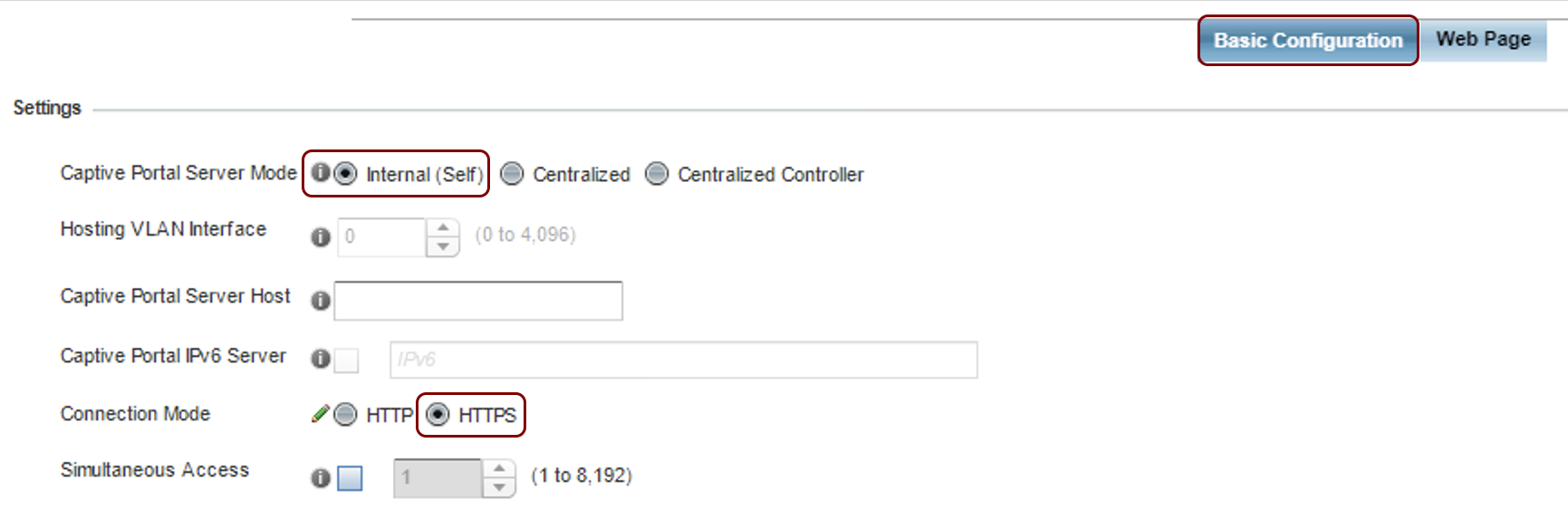
- In the Captive Portal Server Mode field, select the Internal (Self) option.
- In the Connection Mode field, select the HTTPS option.
-
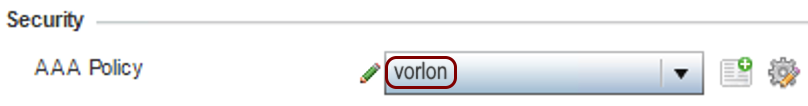
In the Security section below, in the AAA Policy field, click on the
🗎+ icon.
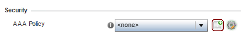
Result: The AAA Policy window opens.
-
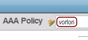
In the AAA Policy field, enter a name for this AAA policy.
-
In the RADIUS Authentication tab, click on the Add button below to add a
new server entry.
Result: The Authentication Server window opens.
-
In the Authentication Server window:
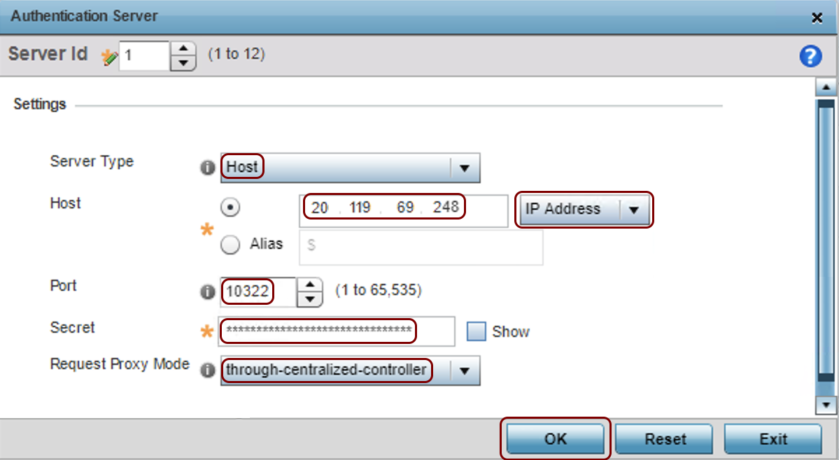
- In the Server Type field, select the Host option.
- In the Host field, select the IP Address option and type the Cloud RADIUS IP displayed in the Cloud RADIUS instance section of Portnox Cloud ().
- In the Port field, type the Authentication port displayed in the same Portnox Cloud section.
- In the Secret field, type the Shared Secret copied from the same Portnox Cloud section using the ⧉ icon.
- In the Request Proxy Mode, select the through-centralized-controller option if you are using a centralized controller (such as the VX 9000 that we used in this example).
- Click on the OK button in the bottom-right corner to save the server configuration and close the Authentication Server window.
-
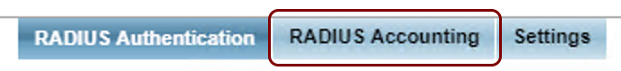
Click on the RADIUS Accounting tab, then click on the Add button below to
add a new server entry.
Result: The Accounting Server window opens.
-
In the Accounting Server window:

- In the Server Type field, select the Host option.
- In the Host field, select the IP Address option and type the Cloud RADIUS IP displayed in the Cloud RADIUS instance section of Portnox Cloud ().
- In the Port field, type the Accounting port displayed in the same Portnox Cloud section.
- In the Secret field, type the Shared Secret copied from the same Portnox Cloud section using the ⧉ icon.
- In the Request Proxy Mode, select the through-centralized-controller option if you are using a centralized controller (such as the VX 9000 that we used in this example).
- Click on the OK button in the bottom-right corner to save the server configuration and close the Accounting Server window.
-
In the AAA Policy field, select the policy that you have just created.
-
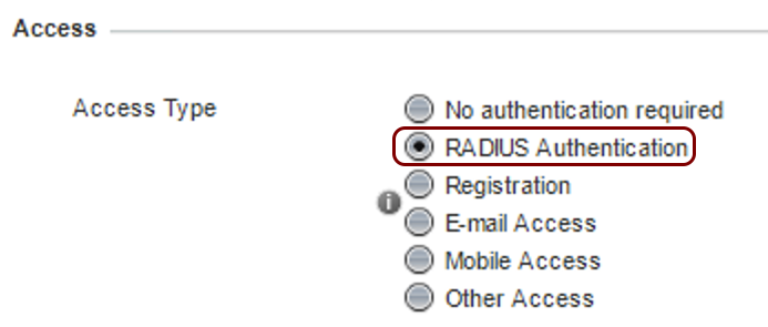
In the Access section, in the Access Type field, select the
RADIUS Authentication option.
-
Scroll down to the DNS whitelist section, and in the DNS Whitelist field,
click on the 🗎+ icon.
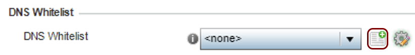
Result: The window for editing DNS whitelist entries opens.
-
In the whitelist entry list window:
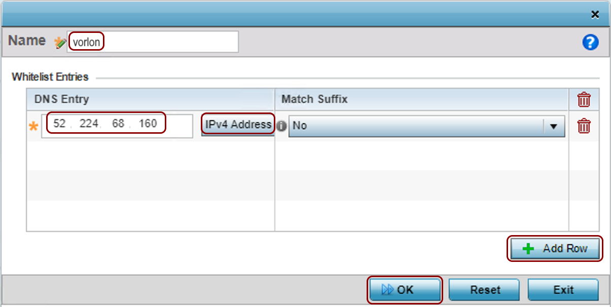
- In the Name field, enter the name for this DNS whitelist.
- Click on the Add Row button.
- In the DNS Entry column, select the IPv4 Address option, and type the first IP (for walled garden) value from Portnox Cloud ().
- Repeat the two steps above for the second IP address.
- Click on the OK button in the bottom-right corner to save the configuration and close the DNS Whitelist window.
Warning:The NAS device must be able to communicate with the walled garden IP addresses at all times. If this communication is blocked in any way, the captive portal will not work, and guest devices will be unable to connect to the network. Before you proceed, verify that all firewalls, ACLs, and any other security measures that could interfere with this communication are configured to explicitly allow the walled garden IP addresses. -
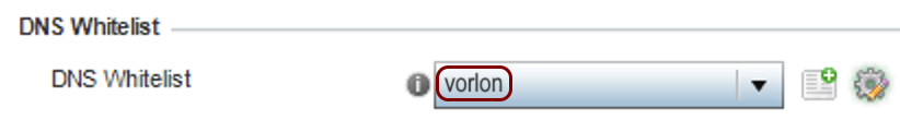
In the DNS Whitelist section, in the DNS Whitelist field, select the DNS
whitelist that you have just created.
-
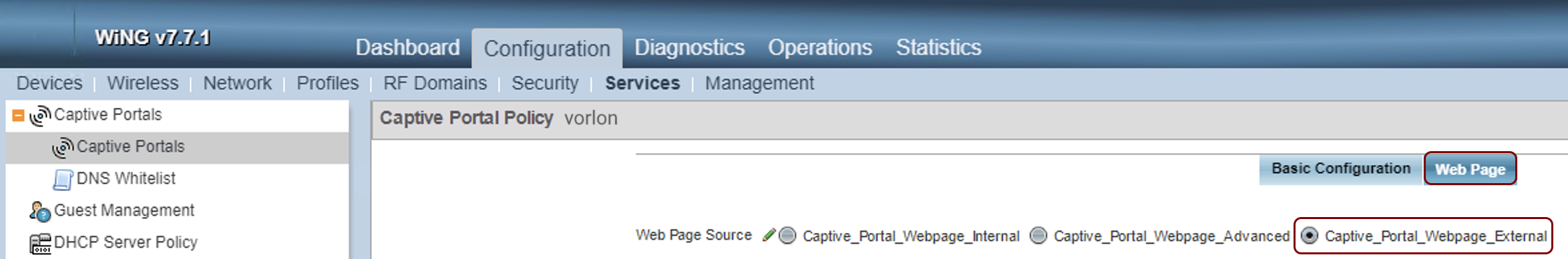
On the top of the Captive Portal Policy pane, click on the Web Page tab
and then in the Web Page Source field, select the
Captive_Portal_Webpage_External radio button.
-
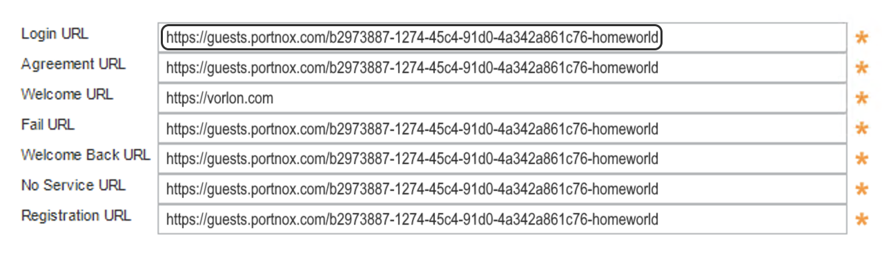
In all URL fields, enter the Captive Portal URL from Portnox Cloud (). In the Welcome URL field, enter a URL that you want to show to the user after
the user successfully authenticates.
Note:WiNG configuration requires you to fill all URL fields, even if most of them are not used by the Portnox Cloud captive portal. That’s why we recommend using the same URL for all those fields.
-
Click on the OK button in the bottom-right corner of the Captive Portal
Policy pane to save the configuration.
-
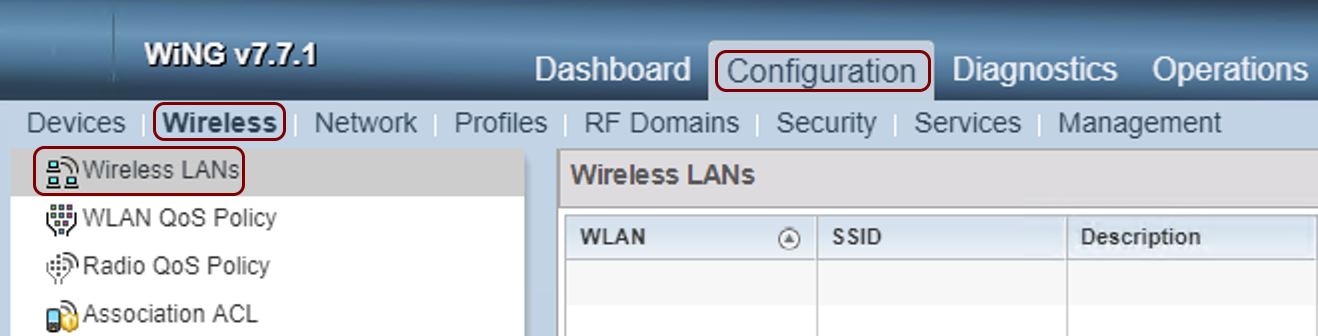
In the WiNG web interface, navigate to: .
-
Click on the Add button on the bottom of the table to add a new wireless LAN.
-
In the Basic Configuration pane:
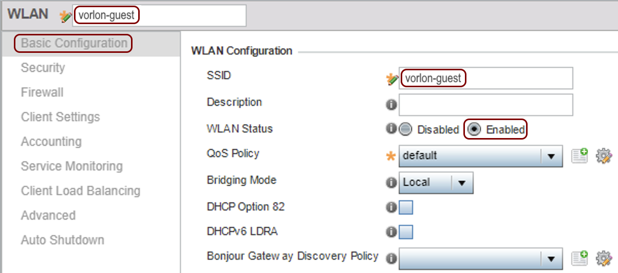
- In the WLAN field, enter a name for this WLAN configuration (it doesn’t have to be the same name as the SSID but we recommend that you use the same name, so that you can easily identify your WLAN later).
- In the SSID field, enter a SSID for this WLAN.
- In the WLAN Status field, make sure that the Enabled button is selected.
-
In the left-hand side menu, click on the Security option, and then in the
Security pane:
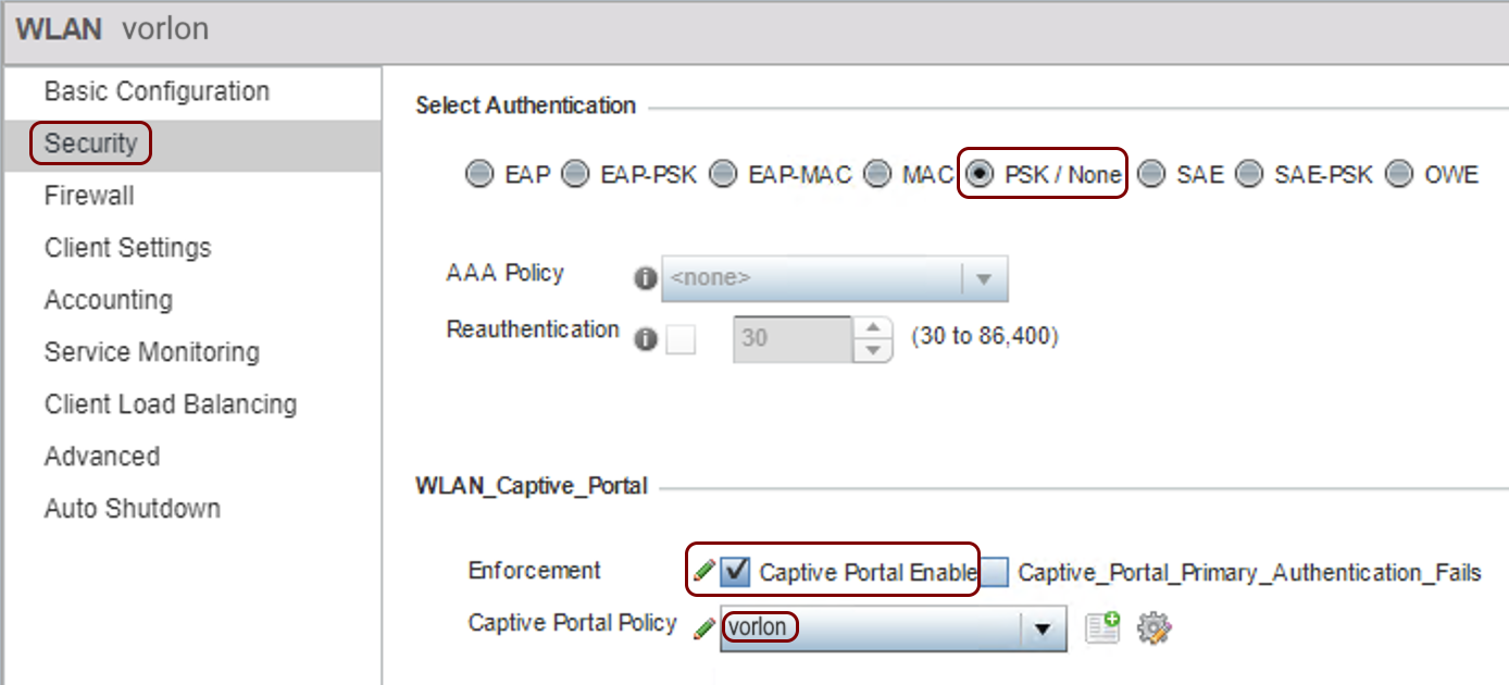
- In the Select Authentication section, select the PSK / None radio button.
- In the WLAN_Captive_Portal section, activate the Captive Portal Enable checkbox.
- In the Captive Portal Policy field, select the captive portal policy that you created earlier.
-
Click on the OK button in the bottom-right corner to save the WLAN configuration.
-
In the WiNG web interface, navigate to: and then click on the name of the profile for the access point model that you want to work with your
WLAN.
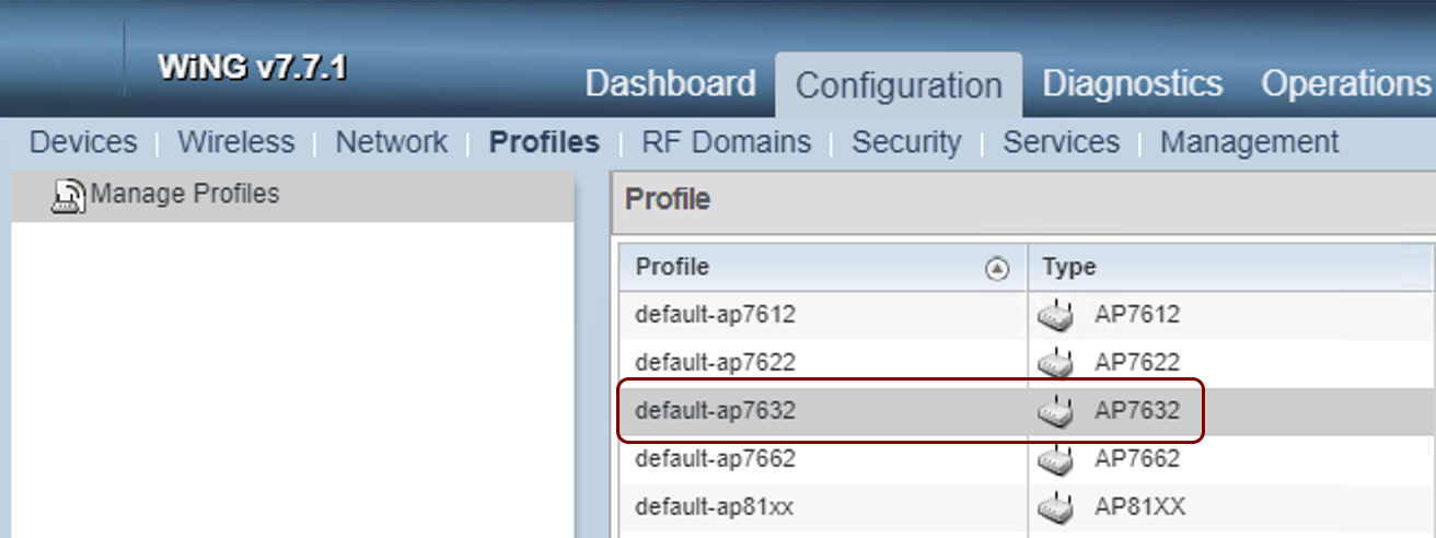
In this example, we selected the AP 7632 profile because we were configuring the AP 7632 model.
-
In the left-hand side menu, click on the option and then click on the radio (frequency) that you want to configure with your new WLAN.
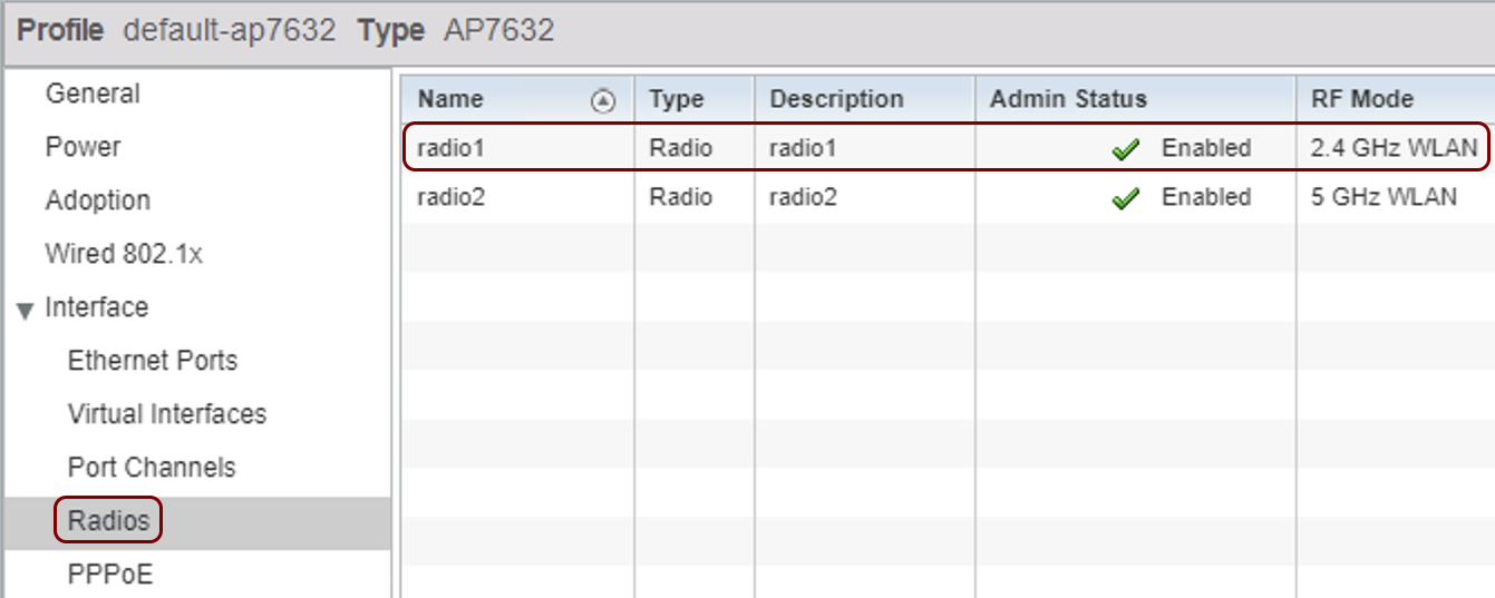
Result: The Radios window opens.
-
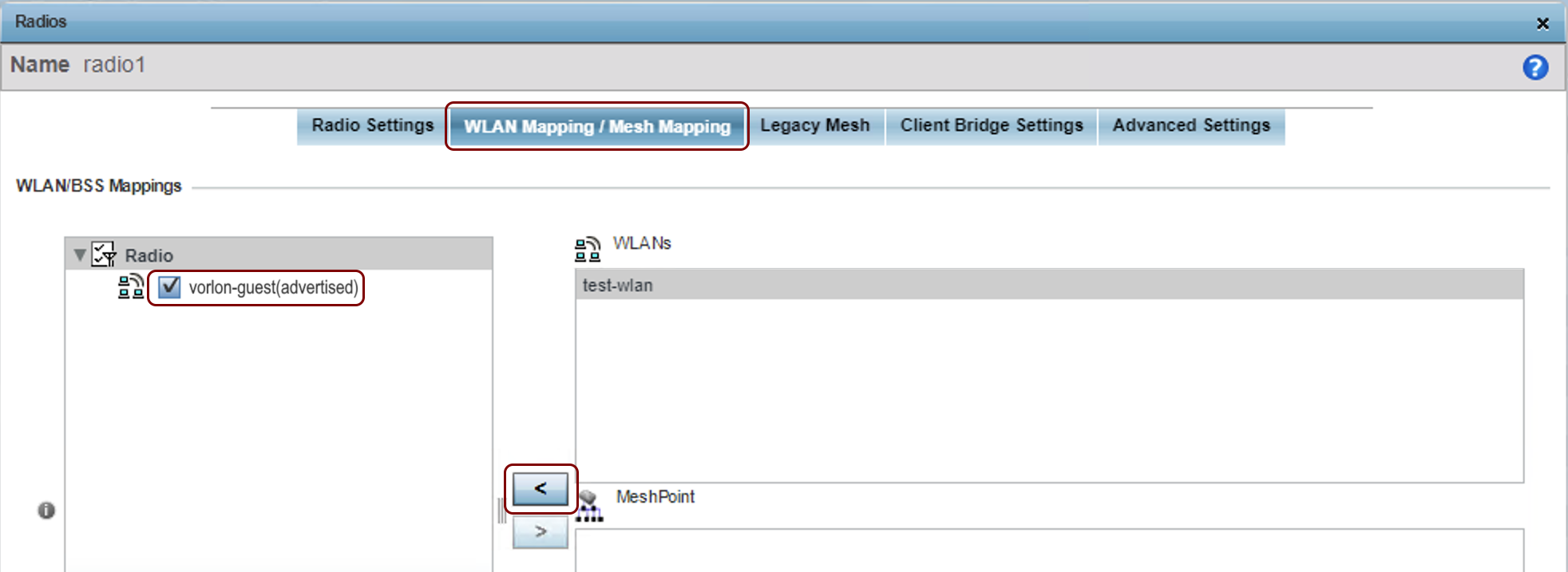
In the Radios window, switch to the WLAN Mapping / Mesh Mapping tab, and
use the < button to move your WLAN from the WLANs list on the
right-hand side to the Radio list on the left-hand side.
-
Click on the OK button in the bottom-right corner to save your radio configuration.
-
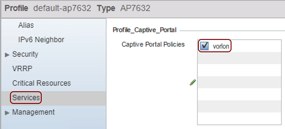
In the left-hand side menu, click on the option and then in the Profile_Captive_Portal field, activate the checkbox next to
the name of the captive portal policy that you created earlier.
-
Click on the OK button in the bottom-right corner to save your access point configuration.
-
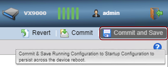
Click on the Commit and Save button in the top-right corner to save and commit your changes to
your WiNG equipment configuration.